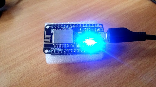
Getting Started with NodeMCU ESP8266 Module
Download and Install NodeMCU ESP8266 module for IoT Applications.
Description:
NodeMCU is a popular open-source IoT platform that uses the ESP8266 Wi-Fi module. Here’s a simple guide to help you get started with NodeMCU using the Arduino IDE.
Step 1: Install Arduino IDE
1. Download Arduino IDE:
- Go to the [Arduino IDE download page](https://www.arduino.cc/en/software).
- Download the version compatible with your operating system (Windows, macOS, Linux).
2. Install Arduino IDE:
- Follow the installation instructions specific to your operating system.
- Once installed, open the Arduino IDE.
Step 2: Set Up Arduino IDE for NodeMCU
1. Add ESP8266 Board Manager URL:
- Open Arduino IDE.
- Go to `File` > `Preferences`.
- In the “Additional Board Manager URLs” field, enter the following URL:
`http://arduino.esp8266.com/stable/package_esp8266com_index.json`.- Click `OK`.
2. Install ESP8266 Board Package:
- Go to `Tools` > `Board` > `Boards Manager`.
- Search for “esp8266” in the Boards Manager window.
- Click on “Install” for the “esp8266” by ESP8266 Community.
3. Select NodeMCU Board:
- Go to `Tools` > `Board`.
- Scroll down and select “NodeMCU 1.0 (ESP-12E Module)”.
Step 3: Connect NodeMCU to Your Computer
1. Connect NodeMCU:
- Use a USB cable to connect your NodeMCU to your computer.
2. Install USB Driver (if necessary):
- For Windows, you may need to install the CH340 USB driver. Download it from [here](https://sparks.gogo.co.nz/ch340.html).
- For macOS, the driver usually installs automatically, but if not, it can be downloaded from the same link.
Step 4: Upload Your First Sketch
1. Open Blink Example:
- Go to `File` > `Examples` > `ESP8266` > `Blink`.
2. Select the Right Port:
- Go to `Tools` > `Port` and select the COM port that your NodeMCU is connected to.
3. Upload the Sketch:
- Click on the upload button (right arrow) in the Arduino IDE.
- Wait for the code to compile and upload. You should see the onboard LED blinking if the upload is successful.
Step 5: Explore More Projects
Now that you have successfully uploaded your first sketch, you can explore more advanced projects. Here are some ideas to get you started:
- Wi-Fi Controlled LED: Control an LED using a web interface.
- Temperature and Humidity Monitoring: Use DHT11/DHT22 sensors to monitor environmental conditions.
- Home Automation: Create a simple home automation system using MQTT.
Project Gallery
All Documents :
Use the Below code for Practice
#define LED D0            // Led in NodeMCU at pin GPIO16 (D0).
void setup() {
pinMode(LED, OUTPUT);    // LED pin as output.
}
void loop() {
digitalWrite(LED, HIGH);// turn the LED off.(Note that LOW is the voltage level but actually
                        //the LED is on; this is because it is acive low on the ESP8266.
delay(1000);            // wait for 1 second.
digitalWrite(LED, LOW); // turn the LED on.
delay(1000); // wait for 1 second.
}
Click Here to Download
Video Tutorial :
Conclusion :
For more projects and tutorials, visit our website. Don’t forget to check out Skill-Hub by EmbeddedBrew for a comprehensive range of courses on embedded systems.


